Solar Panel Specs Explained: Voc, Vmp, Isc and Imp
By Frank Zale · August 23, 2026 · 6 min read
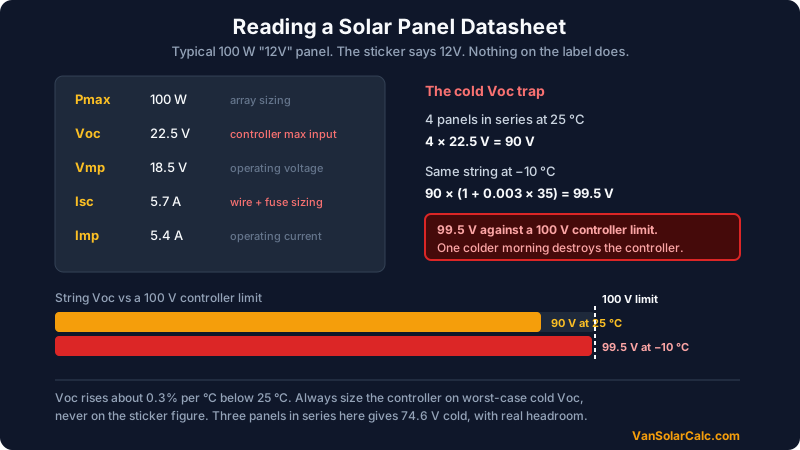
A "100 W 12V panel" is neither 100 W nor 12V most of the time. The sticker is a rating taken in laboratory conditions your roof will never reproduce. The numbers that decide whether your system works, or whether you destroy a charge controller, are on the label on the back.
There are five of them, plus one that matters more than any in cold weather.
The five numbers
| Spec | Name | What it is | What you size with it |
|---|---|---|---|
| Pmax | Max power | Rated output at test conditions | Array sizing |
| Voc | Open circuit voltage | Voltage with nothing connected | Controller max input voltage |
| Vmp | Voltage at max power | Voltage while working | String voltage, controller range |
| Isc | Short circuit current | Current into a dead short | Wire and fuse sizing |
| Imp | Current at max power | Current while working | Normal operating current |
A typical 100 W 12V panel reads roughly: Pmax 100 W, Voc 22.5 V, Vmp 18.5 V, Isc 5.7 A, Imp 5.4 A.
Note that Vmp is 18.5 V on a panel sold as "12V". The nominal label describes the battery it was designed to charge through a controller, not the voltage it produces. Vmp typically sits at 70 to 80 percent of Voc.
Voc: the number that kills charge controllers
Every charge controller has a maximum PV input voltage. Exceed it and you damage the controller, and the damage is not covered by warranty because it is a design error rather than a fault.
Voc is the number to check, not Vmp, because Voc is what appears the instant the array is live and no current is flowing, such as at first light before the controller connects.
In series, Voc adds. Four of the panels above give 4 × 22.5 = 90 V. Against a 100 V controller that looks fine. It is not.
The cold Voc trap
Panel voltage rises as temperature falls. Datasheets give a temperature coefficient of Voc, commonly around −0.3 %/°C, meaning voltage climbs by that percentage for every degree below the 25 °C test temperature.
Take the same four panels on a −10 °C morning, which is 35 degrees below test conditions:
90 V × (1 + 0.003 × 35) = 90 × 1.105 = 99.5 V
That is 99.5 V against a 100 V limit, with no margin at all. A colder morning destroys the controller. This is the single most common way DIY builders kill a charge controller, and it happens on the coldest, brightest morning of the year, which is exactly when everything looks like it should be working.
The fix is to work out worst-case cold Voc before choosing a string layout, and to leave real headroom. Three panels in series here gives 74.6 V cold, which is comfortable.
Isc: what your wire and fuse must survive
Isc is the current the panel delivers into a short circuit, and it is the worst case your wiring has to tolerate.
Wire and fuse sizing uses Isc with a 1.25 safety multiplier, the same continuous-current factor used for charge controller sizing:
Design current = Isc × 1.25
For the panel above, 5.7 × 1.25 = 7.1 A per panel. In parallel, current adds, so three of those panels is 21.4 A of design current, and the combiner wiring and fuse must be rated accordingly.
In series, current does not add. Voltage does. That is the whole trade-off, and it is why series strings use thinner cable. The wiring implications are in series vs parallel.
Reading the temperature coefficients
Datasheets list two or three coefficients. The two worth knowing:
Coefficient of Pmax, around −0.35 %/°C. Output falls as the panel heats. A panel at 55 °C on a summer roof, 30 degrees above test conditions, loses about 10 percent of its rated power. This is part of why the array derate factor of 0.75 exists.
Coefficient of Voc, around −0.3 %/°C. Voltage rises as the panel cools, which is the trap above.
The two work in opposite directions across the seasons. Summer costs you power. Winter costs you controller headroom.
Putting it together
The sequence that avoids expensive mistakes:
- Decide your array size in watts from your daily consumption. See how to calculate your van's daily power usage.
- Choose panels, then read Voc, Vmp, Isc and the Voc temperature coefficient off the datasheet.
- Pick series or parallel based on shade and cable runs.
- Calculate worst-case cold Voc for your string and check it against the controller limit with margin.
- Size the controller current and the wire and fuse from Isc × 1.25. See what size charge controller do I need.
The van solar calculator runs steps 1, 4 and 5 from your appliance list, including the 1.25 margin and the ABYC wire table.
FAQ
What is the difference between Voc and Vmp?
Voc is the voltage across the panel terminals with nothing connected and no current flowing, and it is the highest voltage the panel produces. Vmp is the lower voltage the panel settles at while actually delivering its rated power, usually 70 to 80 percent of Voc. Use Voc to check your controller's maximum input voltage and Vmp to confirm the string sits inside the controller's operating window.
Why is my 12V solar panel producing 18 volts?
Because "12V" describes the battery system the panel is intended for, not its output. A nominal 12V panel typically has a Vmp near 18 V and a Voc above 22 V, and that extra headroom is what allows it to push charge into a 12V battery through a controller. Reading 18 to 22 V at the panel is normal and is not a fault.
Does cold weather increase solar panel voltage?
Yes, and it is the main reason charge controllers fail in DIY builds. Voc rises roughly 0.3 percent for every degree below 25 °C, so a string measuring 90 V at test conditions can reach nearly 100 V at −10 °C. Always calculate worst-case cold Voc for the lowest temperature you expect and choose a controller with margin above it.
What is Isc used for?
Isc is the short circuit current and it sets your wire and fuse sizing, because it is the maximum current the panel can push under fault conditions. Multiply Isc by 1.25 to get design current. In parallel arrays the Isc values add, so a three-panel parallel array at 5.7 A each needs wiring rated for about 21 A.